3. Flow Simulation and Validation Results
Ansys Fluent software was used to conduct this research. Fluid properties are calculated in all cases for the film temperature. The temperature of the film was taken as the average temperature of the fluid inlet and the plate temperature, and the fluid properties at the obtained temperature were calculated and entered into the software with the help of the thermophysical properties tables available in heat transfer books.
For the inlet of the solution domain, we set the Velocity Inlet condition. We have also set the Pressure Outlet condition at the output of the solution domain. The velocity boundary condition is no-slip type. The thermal boundary condition of the upper boundary of the flat plate has a thickness of coupled type. Because the flow is free, the Symmetry condition is also considered for the upper boundary of the solution domain.
According to the presented results, it was found that by increasing the thickness of the plate, the thermal resistance increases and the heat transfer decreases. These simulations were done with two materials, which for aluminum was high due to its thermal conductivity coefficient and its thermal resistance is lower compared to wood, and therefore the heat passing through the coating reaches the screen well. But for wood, due to the low thermal conductivity coefficient, the thermal resistance of the plate increases and a little heat flux passes through it.
At the end of the graph, the heat transfer coefficient in terms of the length of the plate for when the material used in the simulation is wood, the heat transfer coefficient is increasing. The reason for this is that by moving along the plate, the thickness of the coating decreases and its thermal resistance decreases, so at the end of the plate, we will see an increase in the heat transfer coefficient.
Before that, due to the high thickness of the coating and the low coefficient of thermal conductivity of the plate, the thermal resistance of the plate and its coating was high and the heat flux did not pass through it, but with the movement along the plate and the thickness of the plate coating decreased, its resistance decreased and witnessed heat exchange is at the end of it.
As the Reynolds number increases, the displacement heat transfer coefficient increases. The heat transfer coefficient of the displacement of the plane in the turbulence state is higher than in the calm state. Also, in this range of Reynolds number, forced displacement dominates the problem and natural displacement does not have a great effect on the heat transfer rate.
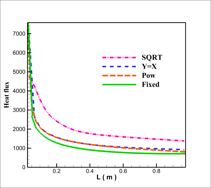
For example, according to the above explanation, we can see one of the results in Figure(1):